Basics

Sunday 3 April 2016

SIMPLE LINE FOLLOWER ROBOT

Hello guys in this tutorial lets see how to make an simple line follower robot with single infra-red sensor. 

Usually for beginners in Robotics this is your first robot to play with Since this robot has some basic functions and basic programming learning this is like learning the A,B,C,D.... of Robotics.

  A line follower is an autonomous Robot which is able to follow a line (black or white) and alter its path based on the shape of the line.


COMPONENTS NEEDED:

  • Arduino UNO
  • one IR-sensor module
  • L293D motor driver
  • metal chassis
  • 2x BO motors
  • 1x caster wheel
  • 2x wheels
  • 2x 9v battery
  • 2x dc battery connectors
  • connecting wires
   The chassis is the body of this Robot, Arduino is the brain of this robot and two dc motors produce motion.


HOW IT WORKS?!


This is a simplest bot with a single sensor so its working principle is also as simple as follows..

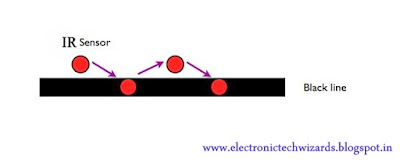
  1.    when the IR sensor sees the black line one wheel of the bot rotates and the bot turns away from the line.
  2.   when the IR sensors sees the white background the other wheel rotates and the bot turns slightly towards the line.

           The above two steps occurs one after other in a repeat mode very fastly in a very short time which gives us the movement of the bot in the path following the black line.

    It just follows the Z pattern turning towards the line and turning away from the line.

LETS MAKE THE ROBOT:


STEP 1:

 Fix the wheels on the metal chassis and mount the Dc BO motors on the back wheels and fix a caster wheel in the front.
connect the L293D motor driver with the arduino and dc motors.

CONNECTIONS:

3,6(l293d) to left motor(output)
11,14(l293d) to right motor(output)

2,7,10,15(l293d) to pins 10,11,5,6 of Arduino(inputs)
Note: if the robot doesn't turn in the particular side of curves properly swap the motor pins connections and try it out.

STEP 2:


Connect your Arduino to your IR sensor.

  1. connect out pin of IR to pin 2 of Arduino
  2. connect vcc of IR to 5v of Arduino
  3. connect gnd of IR to gnd pin of Arduino.

STEP 3:

The programming part....

 Interface your arduino with arduino IDE software and upload the below program.


int lmotorpin1=5;

int lmotorpin2=6;
int rmotorpin1=10;
int rmotorpin2=11;
int sensor=2;
int sensorstate=0;

void setup(){
  pinMode(sensor,INPUT);
  pinMode(lmotorpin1,OUTPUT);
  pinMode(lmotorpin2,OUTPUT);
  pinMode(rmotorpin1,OUTPUT);
  pinMode(rmotorpin2,OUTPUT);
}

void loop(){
  sensorstate=digitalRead(sensor);
  if(sensorstate==HIGH){
    digitalWrite(lmotorpin1,HIGH);
    digitalWrite(lmotorpin2,LOW);
    digitalWrite(rmotorpin1,LOW);
    digitalWrite(rmotorpin2,LOW);
  }
  else{
    digitalWrite(rmotorpin1,LOW);
    digitalWrite(rmotorpin2,HIGH);
    digitalWrite(lmotorpin1,LOW);
    digitalWrite(lmotorpin2,LOW);
  }
}


DOWNLOAD PROGRAM:click here

STEP 4:

connect the power supply to your Arduino and motor driver....

YOUR BOT IS READY TO RACE.......

Sunday 27 March 2016

Obstacle avoiding Robot using Arduino

     Hey guys in this tutorial we will see how to make an autonomous obstacle avoiding Robot.This robot is designed and programmed in such a way that it avoids collision.The robot basically moves in a forward direction and whenever it detects a object/obstacle in its path it takes an diversion and avoids the collision.

COMPONETS REQUIRED:

  • Arduino UNO
  • HC SR-04(Ultrasonic sensor)
  • ultrasonic sensor clamp(optional)
  • L293D motor driver
  • metal chassis
  • 2x BO motors
  • 1x caster wheel
  • 2x wheels
  • 2x 9v battery
  • 2x dc battery connectors
  • connecting wires


WORKING PRINCIPLE:

 The obstacle avoidance robotic vehicle uses ultrasonic sensors for its movements. A UNO of Arduino family is used to achieve the desired operation. The motors are connected through motor driver IC to Arduino uno. The ultrasonic sensor is attached in front of the robot.Whenever the robot is going on the desired path the ultrasonic sensor transmits the ultrasonic waves continuously from its sensor head. Whenever an obstacle comes ahead of it the ultrasonic waves are reflected back from an object and that information is passed to the arduino. The arduino controls the motors  based on ultrasonic signals.

ULTRASONIC SENSOR:
The ultrasonic sensor is used for obstacle detection. Ultrasonic sensor transmits the ultrasonic waves from its sensor head and again receives the ultrasonic waves reflected from an object.The ultrasonic sensor emits the short and high frequency signal. These propagate in the air at the velocity of sound. If they hit any object, then they reflect back echo signal to the sensor. The ultrasonic sensor consists of a multi vibrator, fixed to the base. The multi vibrator is combination of a resonator and vibrator. The resonator delivers ultrasonic wave generated by the vibration. 

 The ultrasonic sensor actually consists of two parts; the emitter which produces a 40 kHz sound wave and detector detects 40 kHz sound wave and sends electrical signal back to the arduino.
The ultrasonic sensor enables the robot to virtually see and recognize object, avoid obstacles, measure distance. To use this sensor to measure distance, the robot's brain must measure the amount of time it takes for the ultrasonic sound to travel.                                              
  Sound travels at approximately 340 meters per second. This corresponds to about 29.412µs (microseconds) per centimeter. To measure the distance the sound has travelled we use the formula: Distance = (Time x SpeedOfSound) / 2. The "2" is in the formula because the sound has to travel back and forth. First the sound travels away from the sensor, and then it bounces off of a surface and returns back. The easy way to read the distance as centimeters is to use the formula: Centimeters = ((Microseconds / 58.2).

LETS MAKE THE ROBOT:

STEP1:

Fix the wheels on the metal chassis and mount the Dc BO motors on the back wheels and fix a caster wheel in the front.
connect the L293D motor driver with the arduino and dc motors.
CONNECTIONS:
3,6(l293d) to left motor(output)
11,14(l293d) to right motor(output)

2,7,10,15(l293d) to pins 2,3,4,5 of Arduino(inputs)

NOTE: you can use an l293d ic or an readymade module,each module differs so check L293D IC pin diagram to make correct connections.


STEP 2:


connect the ultra sonic sensor with your arduino,
pin 8 of arduino to echo pin 
pin 9 of arduino to trigger pin
vcc-5v ,gnd-gnd

STEP3:
Interface your arduino with arduino IDE software and upload the below program.


#define echopin  8 // echo pin
#define trigpin 9 // Trigger pin
int maximumRange = 30;
long duration, distance;

void setup() {
  Serial.begin (9600);
  pinMode (trigpin, OUTPUT);
  pinMode (echopin, INPUT );
  pinMode (2, OUTPUT);
  pinMode (3, OUTPUT);
  pinMode (4, OUTPUT);
  pinMode (5, OUTPUT);
}
void loop ()
{

  {
    digitalWrite(trigpin,LOW);
    delayMicroseconds(2);
    digitalWrite(trigpin,HIGH);
    delayMicroseconds(10);
    duration=pulseIn (echopin,HIGH);
    distance= duration/58.2;
    delay (50);
    Serial.println(distance);
  }
  
  if (distance >= 30 ){
    digitalWrite(2,HIGH);
    digitalWrite(3,LOW);
    digitalWrite(4,HIGH);
    digitalWrite(5,LOW);
    delay (200);
  }
  
  else if (distance >=15 && distance <= 25) {
    digitalWrite (2,HIGH);
    digitalWrite (3,LOW);
    digitalWrite (4,LOW);
    digitalWrite (5,LOW);
    delay (1000);
  }
 else if (distance < 15){
   digitalWrite (2, LOW);
   digitalWrite (3, HIGH);
   digitalWrite (4, LOW);
   digitalWrite (5, HIGH);
   delay (1000);
   digitalWrite (2,LOW);
   digitalWrite (3,LOW);
   digitalWrite (4,HIGH);
   digitalWrite (5,LOW);
   delay (1000);     
 }
}

DOWNLOAD PROGRAM:click here

STEP 4:

connect the power supply to your arduino and motor driver....

YOUR BOT IS READY TO GO.......